
Official Distributor


Authorized partner for premium quality products
Blog
06/11/2014
Turbo Repair Blog Ireland & EU – Technical Guides & Insights
The DOMAT Automotive Engineering Blog delivers expert turbo repair guides, CHRA insights, actuator diagnostics, and in-depth turbocharger technical articles for workshops and professionals across Ireland and the European Union. Our content supports real-world turbo repair, correct part selection, and long-term engine reliability.
- Turbo Repair Ireland expertise
- CHRA technical insights & diagnostics
- Electronic actuator troubleshooting
- Professional knowledge for Ireland & EU workshops
Repair services | DOMAT Automotive Engineering
27/08/2026
Professional Turbocharger Repair & Remanufacturing
Serving trade workshops and private customers across Ireland and the EU, with OEM-level rebuild standards on every turbo we touch.
Get a Repair QuoteOur Repair Process
1
Diagnosis
We identify the true cause of failure before any work begins, so you're not paying to fix the wrong problem.
2
Inspection
Full strip-down and component inspection — shaft, bearings, housings, seals — checked against OEM tolerances.
3
Remanufacturing
Worn or damaged parts are replaced with Melett / HELLA components engineered to original specification.
4
VSR Balancing
Every rebuilt core is precision-balanced to eliminate vibration and extend bearing life under real driving loads.
5
Flow Testing
Post-rebuild flow testing confirms correct boost delivery before the unit ever leaves our workshop.
6
Actuator Calibration
Electronic and pneumatic actuators are calibrated to the exact turbo they're fitted to — no generic settings.
Turnaround, Warranty & Coverage
Fast Turnaround
Most repairs are completed and dispatched within days, not weeks, to keep vehicles and workshops moving.
12-Month Warranty
Every repaired and remanufactured turbo is covered for 12 months, the same as our new units.
Collection or Delivery
We arrange collection of your unit and deliver the finished repair back to you, Ireland-wide and across the EU.
Ireland & EU Coverage
Based in Co. Kerry, shipping and servicing customers throughout the Republic of Ireland and the wider EU.
Trade & Private Customers
Volume-friendly turnaround for workshops, and the same OEM-level care for one-off private repairs.
Free VIN Check – Verify Turbocharger & Car Part Compatibility
09/03/2026
Free VIN Check
Verify Fitment Before You Order
Ordering the correct turbocharger, actuator, CHRA or automotive part can be difficult because many vehicles have multiple engine versions and production changes. With our free VIN check service, DOMAT Automotive Engineering verifies compatibility before you buy.
What You Need to Send Us
Any one of the following is usually enough for us to confirm the correct part — you don't need all of them:
- Vehicle VIN (chassis number) — the most reliable option, since it identifies the exact production build and engine variant
- Engine code — usually stamped on the engine block or listed in the vehicle handbook
- Existing part number — found on the old turbo, actuator or CHRA housing, or on the original invoice
- A clear photograph — of the part's ID plate or casting markings, if the number is worn or hard to read
What We Can Check
The free VIN check covers every category we stock — turbochargers, CHRA cartridges, actuators, actuator position sensors, fitting kits, gasket kits and nozzle rings. If you're not sure which part you need at all, tell us the symptoms your vehicle is showing and we'll help narrow it down first.
How the Check Works
- Send us your VIN, engine code, part number or photo using the button below
- Our team cross-references it against manufacturer fitment data and our own stock records
- We confirm the exact part that matches your vehicle, or flag if more than one variant exists for your build
- You receive a reply by email confirming the correct product, with a link to order once you're happy to proceed
- Avoid ordering the wrong turbocharger or component
- We verify exact compatibility using your vehicle VIN
- Save time and avoid costly returns
- 100% free compatibility check before placing your order
Already know which category you need?
Turbocharger Overspeeding – Causes, Signs and Prevention
09/03/2026
Turbocharger Overspeeding
Causes, Signs & Prevention
Overspeeding happens when a turbocharger's shaft spins faster than its design limit — usually because the engine is drawing more air than the turbo was built to deliver safely. Left unaddressed, it destroys the compressor wheel and takes the whole unit with it. Here's what causes it, how to spot it, and how to stop it happening again.
What Causes Overspeeding?
- Engine tuning changes such as remapping ("chipping") or over-fuelling, which push more air through the turbo than it's rated for
- A torn, split or detached air hose disrupting airflow into the turbo
- A blocked or restricted air intake filter or pipework
- Air leaking in anywhere between the compressor and the engine
- A wastegate or VNT/VGT mechanism set incorrectly, or moving stiffly/restricted
- Worn fuel injectors delivering an inconsistent fuel mix
- Fitting a turbo that isn't the correct specification for the vehicle
- Loss of signal to the electronic actuator controlling the wastegate or VNT
- Operating at high altitude, where reduced air density forces the turbo to work harder
Visible Signs of Overspeeding Damage
- Rippled ("orange peel") compressor wheel surface — a telltale texture change on the blade faces caused by excessive rotational stress
- Inducer blade damage — chipping or deformation at the blade's leading edge
- Partial blade loss — sections of the compressor wheel breaking away
- Burst wheel — complete structural failure of the compressor wheel under extreme overspeed
- Fatigue fractures — cracking across the blades from repeated stress cycles, even without an immediate catastrophic failure
How to Prevent It
- Keep the turbocharger in its original, unmodified state — don't alter internal clearances or components
- Only fit a turbo specified for that exact vehicle and engine, confirmed by engine code or OE reference
- Check the air intake pipework regularly for leaks, splits or restrictions
- Make sure the wastegate or VNT linkage moves freely and is correctly calibrated
- Verify electronic sensors and the ECU are reporting correctly — a faulty signal to the actuator can cause overspeed conditions
- Avoid remaps, chip tuning or over-fuelling that push airflow beyond the turbo's rated capacity
- Common causes of turbo overspeeding
- Visible signs of compressor wheel damage
- How to prevent turbocharger failure
If your turbo shows any of the signs above, replacing it correctly matters as much as replacing it at all:
Blocked DPF Causes Turbo Failure: Symptoms & Prevention Guide
18/02/2026
Blocked DPF Causes Turbo Failure
Symptoms, Testing & Prevention Guide
By Tomasz Kozien, DOMAT Automotive Engineering
There are many articles and technical documents relating to how a faulty turbo can lead to DPF damage. However, the DPF is actually responsible for more turbo-related failures than you might think. Here we explore what effect a blocked DPF can have on a turbocharger.
DPFs (Diesel Particulate Filters) were first introduced in January 2005 with the Euro 4 emission standard, where diesel particulate levels were reduced to extremely low levels to reduce the allowable amount of particulate matter (PM) released into the atmosphere. Reducing the size of PM from the combustion process to this level was not technically possible, so this meant all diesel vehicles after September 2009 were fitted with a filter to capture soot and other harmful particles, preventing them entering the atmosphere. A DPF can remove around 85% of the particulates from the exhaust gas.
A blocked DPF will not work correctly. To clear this blockage there are two types of regeneration which are commonly used to remove the build-up of soot. Newer vehicles engage active regeneration, which is the process of removing the accumulated soot from the filter by adding fuel post combustion to increase exhaust gas temperatures and burn off the soot, providing a temporary solution. Passive regeneration takes place automatically on motorway-type runs when the exhaust temperature is high. Many manufacturers have moved to using active regeneration as many motorists do not often drive prolonged distances at motorway speeds to clear the DPF. Constant short distances are not good for the turbo or exhaust system.
Fix the DPF Before You Fit a New Turbo
If a blocked DPF caused the original turbo failure and it isn't cleared or replaced first, a brand-new turbocharger will be exposed to the exact same back pressure and exhaust temperature that destroyed the last one. Fitting the replacement before addressing the DPF is one of the most common reasons a "new" turbo fails again within weeks or months.
Driver-Facing Symptoms of a Blocked DPF
Before any turbo damage becomes obvious, these are usually the first signs something's wrong upstream:
- DPF warning light on the dashboard
- Engine management light, sometimes flashing
- Noticeable loss of power or the vehicle entering limp mode
- Rough idle or unusually high fuel consumption
- Regeneration cycles that repeatedly fail to complete, or a strong smell during regeneration
- Black or excessive exhaust smoke
- Whistling or unusual turbo noise as back pressure builds
So, what happens to the turbo when a DPF is blocked?
A blocked DPF prevents exhaust gas passing through the exhaust system at the required rate. As a result, back pressure and exhaust gas temperatures increase within the turbine housing. Increased exhaust gas temperature and back pressure can affect the turbocharger in a number of ways, including:
- Problems with efficiencies
- Oil leaks
- Carbonisation of oil within the turbo
- Exhaust gas leaks from the turbo
How Back Pressure Is Actually Tested
Guessing from symptoms alone isn't reliable enough to confirm a DPF-related turbo failure — back pressure needs to be measured directly:
- Exhaust back-pressure gauge — a pressure gauge is connected to a port before the DPF (often via the oxygen sensor or a dedicated test point) and readings are taken at idle and under load, then compared against the manufacturer's specification
- Differential pressure sensor data — most vehicles already have a DPF differential pressure sensor; live diagnostic data from this sensor shows the pressure drop across the filter, which rises as the DPF blocks
- Boost pressure comparison — actual boost readings are checked against expected values for the engine; boost that's noticeably below spec, alongside high back pressure, points to restriction rather than a turbo fault
- Visual DPF inspection — where possible, the filter itself is inspected or its ash/soot loading value checked via diagnostics to confirm blockage rather than relying on pressure readings alone
How to spot a turbocharger that has suffered from DPF problems:
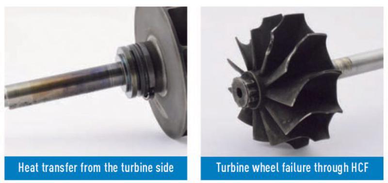
Discolouration of parts within the core assembly (CHRA)
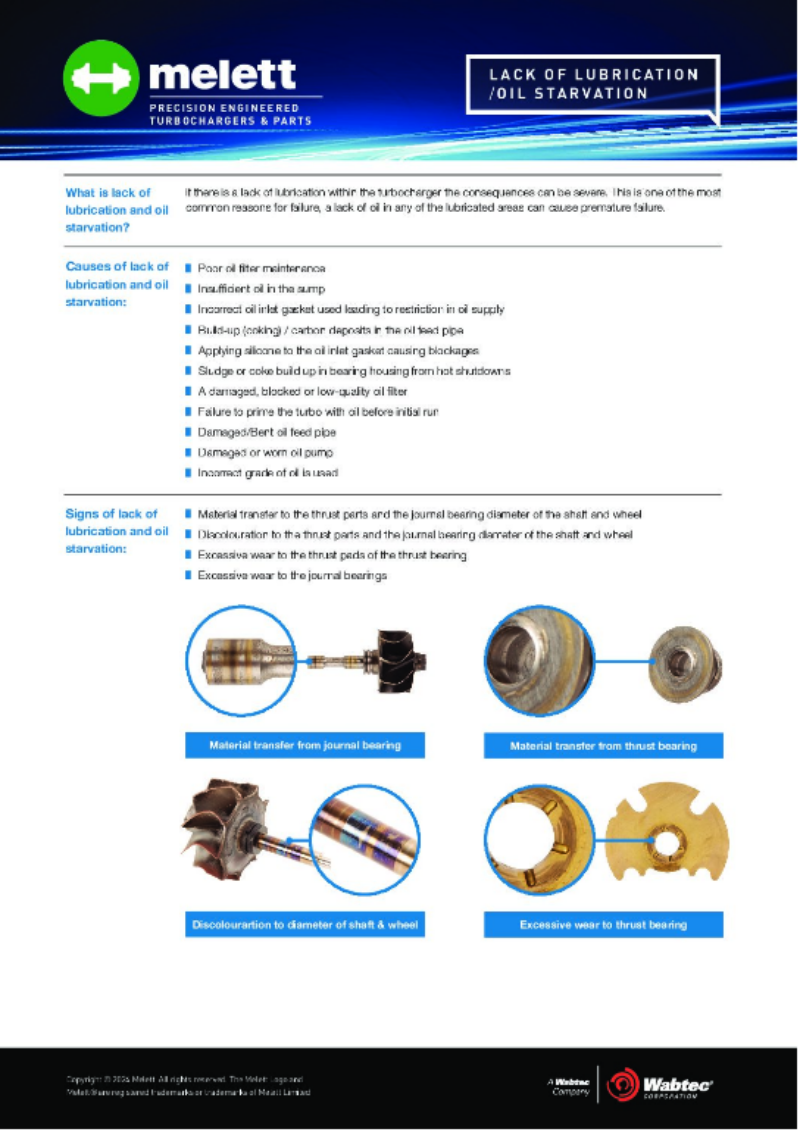
Usually with evidence that the heat is transferring through the CHRA from the turbine side. This excessive temperature within the CHRA is caused by back pressure forcing the exhaust gas through the piston ring seals and into the CHRA. The high temperature exhaust gas can prevent efficient oil cooling within the CHRA and even carbonise the oil, restricting oil feeds and causing wear to the bearing systems. This type of failure can often be mistaken as a lack of lubrication or contaminated oil.
Carbon build-up in the turbine side piston ring groove
Caused by the increased exhaust gas temperatures.
Oil leaks into the compressor housing
Can be seen as a consequence of exhaust gas forcing its way into the CHRA from the turbine side and forcing oil through the oil seal on the compressor side.
Exhaust gas forced through smallest gaps
A blocked DPF can force exhaust gas through the smallest of gaps, including the clearances in the bearing housing VNT lever arm and turbine housing waste gate mechanisms. If this occurs, carbon build-up in these mechanisms can restrict movement of the levers, affecting performance of the turbo. In some cases soot build-up can be seen on the back face of the seal plate where the exhaust gas has been forced through.
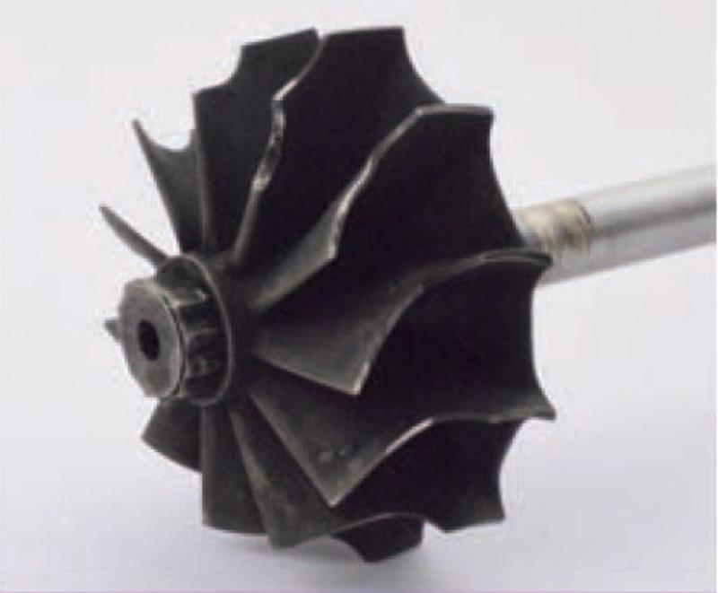
Turbine wheel failure
Caused by high cycle fatigue (HCF) due to temperature increase.
How can you prevent these failures from occurring?
As a starting point, it is essential to identify the failure mode and determine whether a DPF-related issue is the root cause. If the entire rotor assembly is okay, and there are some signs of overheating towards the turbine side of the core assembly, then the failure is likely to be caused by excessive exhaust gas temperatures. High amounts of carbon build-up within the VNT mechanism and lever arms indicate a blocked DPF, and the driver may experience turbo lag or over boost of the turbo.
To help prevent turbo failure caused by DPFs:
- Test for and confirm whether the DPF is actually blocked, using back-pressure and differential pressure data as above — don't assume from symptoms alone
- Contact a DPF specialist for advice
- Replace the DPF with a high quality replacement — lower cost DPFs will often not operate as efficiently as the original, which can replicate the environment of a blocked DPF
- Only once the DPF issue is resolved, replace the turbocharger core assembly to prevent possible oil leaks
- Check the actuator achieves its full range of movement, particularly if electronic, as internal components could be worn
Important: It takes time for a DPF to block, sometimes years. Once blocked though, turbo failure can occur very quickly. If you don't check for a DPF issue when installing a replacement turbo, there is a very high chance the replacement turbo will suffer the same failure, as it will be subject to the same operating environment as the previous unit.
Replacing a turbo damaged by a blocked DPF?
REA & SREA Electronic Actuator Failure: Symptoms, Causes & FAQ
16/02/2026
REA & SREA Electronic Actuator Failure
Symptoms, Causes & Frequently Asked Questions
REA (Rotary Electronic Actuator) and SREA (Simple Rotary Electronic Actuator) units control variable geometry vane movement on a wide range of turbochargers. This guide answers the most common questions about diagnosing, repairing and replacing them correctly.
In Short
- REA and SREA actuators are not interchangeable — each is calibrated in software to one specific turbocharger
- An "actuator fault" can actually be caused by the turbo itself — sticking vanes overload and burn out the actuator motor
- The black cap electronics can't be repaired or soldered — a faulty one means replacing the whole calibrated unit
- If the vanes or nozzle ring are damaged rather than just fouled, the actuator alone won't fix the problem — the turbo needs inspecting too
What are the symptoms of possible electronic actuator failure?
There are a few factors which determine an actuator failure:
- Flashing engine management light
- A complete loss of power, causing the vehicle to go into limp home mode
- Low boost
- Over boost
- Noise from the turbocharger
- Fault codes
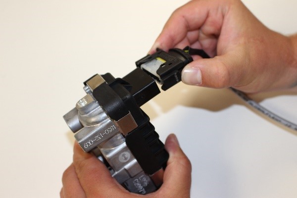
How to identify a REA/SREA connector?
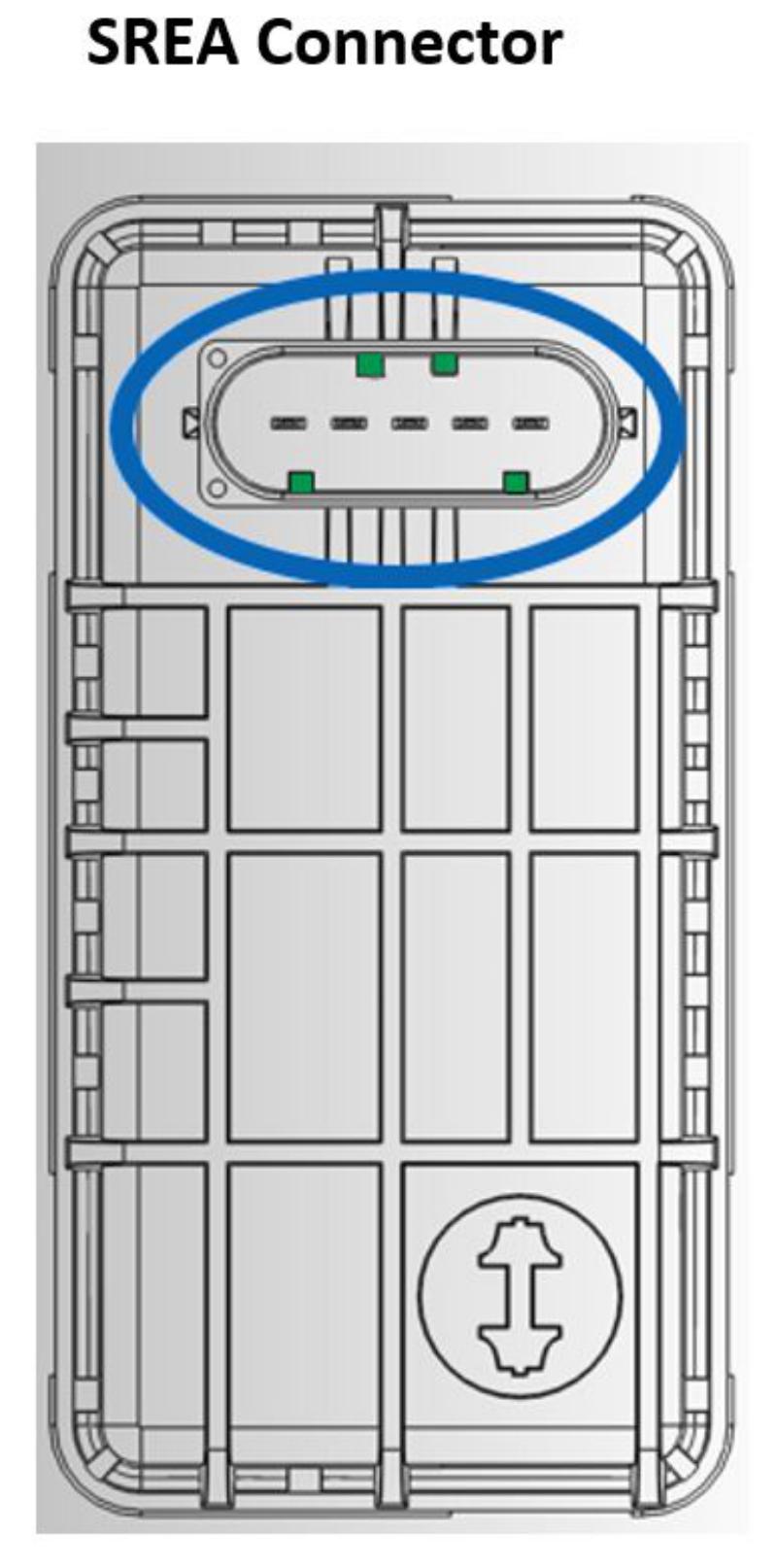
There are two types of Electronic Actuators. The two types (SREA/REA) can be identified by the different orientation of their connectors.
Please note: Avoid touching the connectors to reduce the risk of damage.
My diagnostic equipment has identified a fault with the turbocharger — is an electrical fault responsible?
Checking ECU error codes and researching these codes is critical and can help you identify the root cause very quickly. Turbos are on the same circuit as other sensors, and it may well be those at fault, not necessarily the turbo. We have seen examples of turbo faults being registered on the diagnostic tool where, upon investigation, the injectors were actually at fault.
Check the vehicle history for past issues, such as previously recorded ECU error codes and replaced engine components — especially those linked to the turbo.
With the engine turned off and cold, check if the linkage can be seen or felt between the SREA/REA (a small black box attached to the intake side of the turbo) and the bearing housing lever arm. If accessible, check for free movement at each end of the linkage — there should be a small amount of play. Also check for corrosion which may be restricting movement, and confirm the linkage is not detached at either end.
Please note: Use the locking tabs to release the electrical connector to avoid damage.
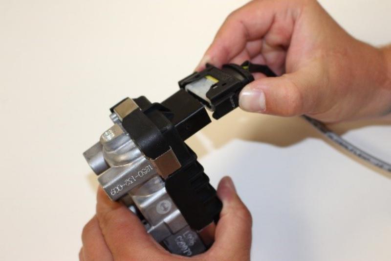
Further investigation:
- Is the REA/SREA electrical connector firmly located? Avoid pulling the wiring directly as this could cause damage.
- Are the locking tabs on the connector damaged?
- Are there signs of water ingress? Check for water or staining below the connector seal and in the REA/SREA connector (removal of the connecting wires is required to do this).
- Are the connector walls or seal damaged? Check the REA/SREA connector walls for damage or cracks.
- Are the wires within the harness connected properly and unused positions sealed?
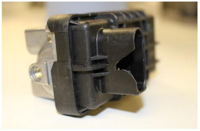
Check the REA/SREA connector wall for damage or cracks.
Finally…
- Switch on the ignition without cranking the engine — does the electronic actuator move freely? Note: some actuators will not move until the engine is running.
- Do any warning lights appear on the dashboard?
- Start the engine and again listen for actuator noise; if possible, visually check for movement of the actuator.
- Check again for any warning lights on the dashboard. If lights appear and movement of the actuator can be seen, there may be an electronic fault elsewhere on the vehicle.
- Switch the ignition off — the actuator arm should move rapidly to the "safe" position. On some occasions the actuator arm may continue its sweep to clear the nozzle vane path, depending on the application.
If the steps above have been followed and all connectors are in good condition, movement of the actuator is free, and there are no signs of water ingress, then it is highly likely the fault lies somewhere other than the turbo.
If the electronic actuator has failed, should I check the turbocharger?
It is vital to check the turbocharger even if the problem appears to be an electronic actuator-only issue.
SREA and REA actuators can fail because the variable geometry mechanism sticks due to sludging or carbon build-up. When this happens, it pulls a higher current through the motor than it is designed for, causing the motor to burn out or the plastic worm gears to fail. This restriction can reduce boost pressure and may result in the vehicle being put into limp home mode.
When repairing the electronic actuator, the worm gear and motor must be the correct ratio to avoid immediate failure. In most failures, the black cap and electronics within are unaffected by gearbox failure and can be reused.
If the actuator has failed to open the nozzle ring assembly vanes under acceleration, the turbo will also fail to operate efficiently. Vanes set to a closed position can cause choking of the engine or overspeeding of the turbine. Conversely, vanes that are open more than required will cause excessive lag and slow turbo response.
When it's more than the actuator: if the vanes are seized rather than just fouled, worn beyond specification, or the nozzle ring itself is damaged, a new actuator will move correctly but the underlying restriction remains. In that case the nozzle ring, CHRA, or full turbocharger needs inspecting and likely replacing alongside the actuator, not instead of it.
Are electronic actuators interchangeable?
SREA/REA electronic actuators are highly complex and intricate. They are not interchangeable with different gearboxes or black caps. The calibration settings are programmed in the software within the black cap and are unique to each individual turbocharger. Even loosening the retaining bolts on the actuator will take it outside of specification.
Always confirm your engine code or the turbo's OE reference before ordering a replacement — send it to us and we'll match the correct calibrated unit rather than a generic equivalent.
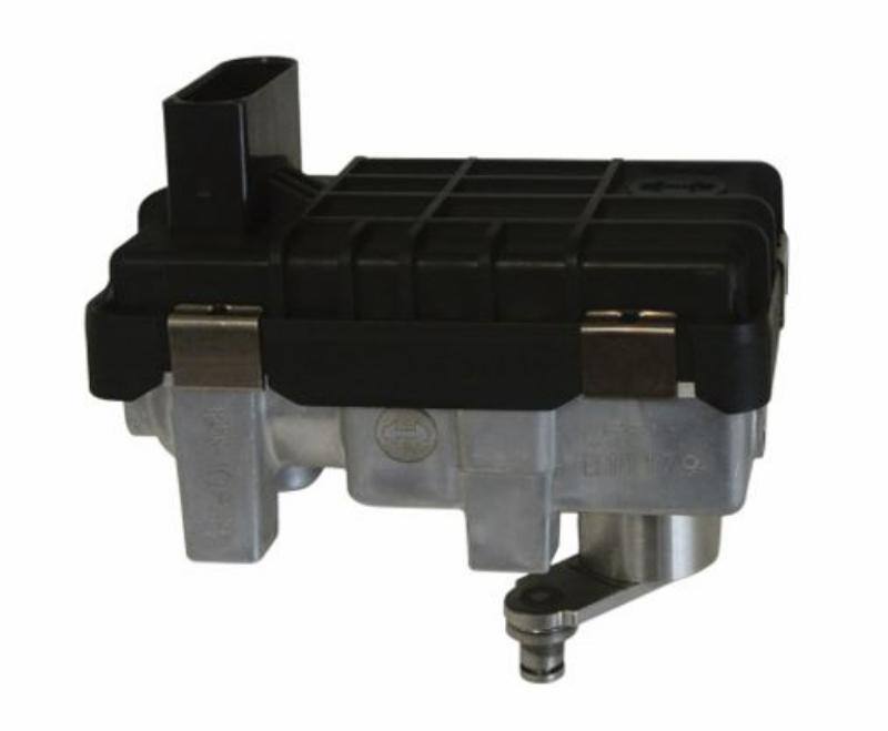 The black cap is damaged — can I repair it?
Each turbo is calibrated differently and the electronics within each cap are programmed specifically for that turbo, making it a non-serviceable part. In this instance you would need to replace the complete SREA or REA unit with the correct calibration settings. Incorrect calibration of the electronic actuator when assembled on the turbocharger can result in poor performance or complete failure.
Can I use solder to fix broken connections in the black cap?
Soldering to repair broken connections in the gearbox and black cap is not advised. Solder is susceptible to cracking in environments with temperature variance and vibration. For this reason, the motor, motor choke assembly, and connectors must not be spot welded.
What other factors can cause my actuator to fail?
Mishandling of the turbo
If the turbo connector is knocked or banged it will break, and the whole unit will need replacing.
Water ingress
The location of a turbo in the engine compartment can make the electronic actuator susceptible to water ingress. The actuator can become rusty and contaminated, giving incorrect signals and ultimately failing.
Board connectors
The wire connectors can expand and contract over time, eventually breaking and causing actuator failure. This fault can often go undetected during repair and workshop testing, as it may only become apparent once a temperature change occurs.
Engine vibration
Constant vibration from the vehicle can gradually wear the electronic actuator out, causing it to fail over time.
Need a REA/SREA actuator or position sensor?
RACH Turbocharger Remanufacturing Process
21/06/2016
RACH Original Remanufactured Turbos
"The RACH brand is synonymous with quality, performance, and reliability…We are bringing great value to the global aftermarket with our remanufactured turbo range.
"When replacing turbos, especially those from the technologically sophisticated VNT range, there's no need to risk poor performance or engine damage that may result from using non-original poorly assembled parts. With 'RACH Original Remanufactured' we provide another choice for the best possible support of a mature product line-up."
Precision Engineering
The complexity of a VNT turbo architecture is underlined by component tolerances that can be just 4 microns - the same as a particle of dust and 17 times smaller than a human hair - with rotational speeds reaching up to 250,000 rpm.
Technical Excellence
RACH is leveraging its unique technical knowledge and production know-how to deliver turbocharger units matching the engine management system requirements and emissions standards through its original assembly, calibration and balancing processes.
Complete Package
"With a RACH remanufactured turbo, everything is included - technical expertise and support, same warranty as a new turbocharger... and the peace of mind that comes from dealing with a world-leader in turbo technology."
Quality Standards
- Inspected to same standards as original new parts using original production drawings
- Re-assembled, balanced and calibrated to same specifications as original new parts
- Individually set up on a turbine flow bench exactly as new turbos
- Always fitted with new original components, such as actuators, compressor wheels, bearing systems, seals, O-rings, piston ring seals, bolts and clamps
- Updated with any components superseded since original design
CIMAT Flow Bench Testing
21/06/2016
Why Flow-Bench Testing and VNT Calibration Matter
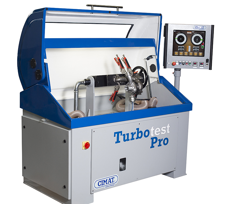
A flow bench simulates real exhaust and boost conditions to test a turbocharger's actual airflow performance and vane behaviour — something you can't confirm just by moving the actuator arm by hand. It's how we verify a rebuilt or newly fitted turbo will perform correctly before it ever goes back on a vehicle.
Why Actuator-Arm Movement Alone Isn't Enough
Checking that an actuator arm moves freely by hand only confirms the mechanism isn't seized — it says nothing about whether the vanes are hitting the correct position under actual boost pressure, or whether the ECU's calibration data matches the fitted geometry. A turbo can pass a manual arm-movement check and still overboost, underboost, or trigger fault codes once it's actually running.
How Incorrect Vane Settings Affect Boost and Turbo Speed
In a VNT/VGT turbo, vane angle directly controls how much exhaust gas energy reaches the turbine wheel. Vanes set even slightly out of specification change turbine speed — too closed and the turbo overspeeds and overboosts, risking compressor wheel damage; too open and boost response is sluggish, with the turbo unable to reach the pressure the engine needs. Flow-bench testing measures this directly instead of relying on a visual or manual check.
Why Electronic Actuators Need Accurate Calibration
Electronic actuators are calibrated to the ECU's expected position values for a specific turbocharger and vehicle application. Fitting a replacement actuator without recalibrating it — or fitting one that isn't a genuine match for the original — means the ECU's commanded position and the actuator's actual position can drift apart, producing the same overboost/underboost symptoms as a mechanical vane fault, even though the hardware itself is fine.
Our Equipment and Which Turbos Need Flow Testing
We test on a CIMAT flow bench, which measures airflow, boost response and vane/actuator movement under simulated running conditions rather than at rest.
Flow testing is carried out on every VNT/VGT turbocharger we remanufacture or repair, and on any CHRA replacement or electronic actuator fitment where vane geometry or actuator calibration could be affected. Fixed-geometry turbos without a variable vane mechanism don't require this specific test, though they're still checked for balance and airflow.
How This Prevents Repeat Failure
Most repeat turbo failures after a repair trace back to something that was never actually tested under running conditions — a vane setting slightly off spec, or an actuator calibrated to the wrong reference. Flow-bench testing catches these before the unit is refitted, rather than the vehicle owner discovering them on the road through overboost, underboost, or a returning fault code.
Related categories:
Go with the Flow… The need for an Air Flow Rig
21/06/2016
Go with the Flow… The need for an Air Flow Rig
There has been an ongoing debate for many years between the original turbocharger manufacturers and the turbocharger repair industry, over whether a turbo can be repaired.
This debate has been raging for over 10 years. Some OEM turbo manufacturers pulled out of the repair market around 2004 – at this time their argument was that most repairers did not have the correct specialist balancing equipment for the new higher speed turbos.
Over the last decade, vehicle technology has continued to improve to reduce emission levels in order to meet the Euro 4, 5 then 6 regulations. As a result of these changes, engine and turbo technology has increased in complexity, and the settings and control of advancements, such as the Variable Nozzles, have become more critical to the correct operation of the turbo.his is now presenting new challenge turbo repairers as the correct setting of the turbo on later models, now requires further specialist equipment in the form of an Air Flow Rig.
What is a Variable Nozzle Turbo?
When a turbocharger is matched to an engine, the Engineers have to balance the low speed response with high speed efficiency. The variable nozzle (also referred to as a variable geometry), is designed to change the exhaust gas inlet area with the engine speed to closely match the desired boost requirements of the engine. For low speed response, the nozzle vanes move to the 'closed vane' position to reduce the nozzle area – this increases gas speed through the turbo giving improved response at low engine speeds – similar to squeezing the end of a hose pipe to make the jet of water more powerful. As the engine speed increases, the actuator moves the nozzle vanes to the fully open position to maximize the exhaust gas flow.
Vane Setting Accuracy
When the first variable nozzle turbos were launched, it was a step change in turbocharging technology. Air mass sensors and ECU's were programmed to manage the whole engine system, however relative to the current engines, tolerances for acceptable air flow were set quite high. When setting up a new turbo, vane setting positions are set using accurate air flow equipment, which ensures that the 'minimum vane opening' position is set to allow a specific mass of air flow through the vanes. If the vanes are too closed, this can cause choking of the engine and overspeeding of the turbine. If it is set too large, the turbo will have too much 'lag' and not respond as well as it should.
Traditionally, turbo repair workshops did not use an air flow rigs to correctly set the flow. The actuator position was set based upon an accurate measured position of the actuator arm. This produced acceptable results and allowed the repairers to keep on repairing.
In reality, this method of setting the vanes can produce quite large inaccuracies in the flow of air. The actuator arm measurement is set against a cast finish on the bearing housing, the position of which is not accurately controlled during manufacture. However, as the engine would accept quite a large tolerance of air flow, the repaired turbo still performed well compared to the broken turbo which it replaced, so the vehicle owner was still happy with the results. On older turbo repairs, the variable nozzle position had to be a long way out before the performance was unacceptably affected or for the ECU to flag a problem. From an OEM perspective, this is not acceptable and is the reason for their lack of support of repairing.
The need for accurate air flow setting of turbos was well understood by reputable repairers, and hence some quality repairers developed their own air flow equipment to accurately set their turbos, resulting in a reduction in warranties and the ability to build on their reputation as a quality repairer.
Today's Turbos
In more recent years, as engines have improved to meet tighter Euro emission regulations, the control over the whole air / fuel system has improved dramatically. Many premium brand vehicles have moved to electronic actuation which gives positional feedback to the ECU. Some more advanced turbo controllers now sit within the CANbus talking directly to the injection system and air mass sensors, to respond more quickly to engine demands. For these turbos, the settings are either correct and accepted by the ECU – or not which results in warning lights, limp home mode or refusal to start.
As more of the Euro 5 compliant vehicles enter the aftermarket, problems will arise and for some turbo models, we have already reached the point where flowing the turbo is a necessity and only possible by workshops who have the correct equipment. However, this will naturally mean that older turbos also become more widely repaired using air flow equipment, which will bring further improvements to the market.
Making the Right Choice
Traditionally, in the turbocharger aftermarket the customer had a choice between a new OE turbo and a remanufactured turbo. Over the past 10 years the turbo repair market has changed significantly with the number of new repairers entering the market and the number of suppliers of parts. What we now have is three tiers, a new OE turbo, a high quality remanufactured turbo repaired using quality parts and the correct equipment, and a poor quality repaired turbo, using inferior quality low cost parts. There will always be a market for all three options depending upon the vehicle owner's requirements.
It is important that garages understand that there are different levels of quality for repaired turbos and therefore a different level of associated cost. When outsourcing turbo repairs it is crucial to consider the real cost of replacing a turbo and to educate your customer about the different options and associated risks for going lowest cost vs paying a little more for quality, so they can make informed decisions. Who pays for the time to fit the second replacement? What if it damages other parts of the engine?
Many turbo specialists already have a flow rig and are repairing turbos to an excellent standard. It is a fact that warranties are reduced when turbos are repaired using quality parts as well as the correct repair equipment.
Is the Turbo Price Right?
21/06/2016
Is the Price Right?
Today's automotive repair industry is faced with an overwhelming range of repair parts. Amid claims of exceptional quality at extraordinarily cheap prices, here Martyn Howorth, Sales Director, Melett Ltd., explores the reasons why some turbocharger components are offered at such low prices, and what the real cost of these low quality parts means to the repair industry.
Raw Material Costs & Global Pricing
As global demand for turbochargers increases, the raw materials used in the manufacture of the components are becoming more expensive. Raw material prices have conventionally been determined by the Global Price Index (GPI), with stockists adding their margin before selling to the mass market.
Using a turbocharger turbine wheel as an example, a major part of the cost of the turbine wheel is based upon the current market cost of Nickel – the main component of the Inconel material, plus the manufacturers mark-up. The price of an Inconel wheel will be agreed on a monthly basis, if the GPI increases by 3% for example, stockists reserve the right to charge more for the raw materials, therefore increasing the global cost for manufacturers. Nickel is a popular element used during the manufacture of many automotive components, and in particular turbine wheels, as it is able to withstand the tough operating conditions and extreme temperatures of a modern turbocharger.
The Quality Compromise
In countries where the market is saturated with many new parts suppliers, under cutting margins is now common practice resulting in companies selling low quality products at rock bottom prices. In China, for example, there is a limited supply of nickel, and therefore stockists in that marketplace can sell it at a premium, as a result this should be reflected in the market price of a turbine wheel. However, the way many manufacturers are producing turbine wheels at a lower cost is to simply use a lower grade of Inconel with less nickel. This will significantly reduce the wheels overall performance and durability, leading to unreliable repairs and premature failure. Historically, low cost manufacturers were only concerned with undercutting each other's margins, however in today's environment they are now forced to reduce the quality of the cast materials in order to compete with each other. As a result we are seeing a reduction in quality.
Understanding True Value
High quality repair parts will always hold a premium in comparison to the lower quality alternatives. It is important to understand the point at which cutting margins turns into reducing quality. Every component has a minimal price point and anything lower than that point can only be achieved by using lower grade raw materials in the manufacturing process.
Cast vs MFS Compressor Wheels: Flatback to Extended-Tip
21/06/2016
Cast vs MFS Turbo Compressor Wheels
Flatback, Superback and Extended-Tip Designs Explained
Modern engines spin turbochargers faster and at higher boost than ever before, and compressor wheel design has had to keep pace. Here's how wheel design evolved to survive those forces, what Machined-From-Solid actually changes, and when it's genuinely worth upgrading from a cast wheel.
Why Cast Wheels Reach Their Limit
Compressor wheels are made from aluminium because it's roughly a third the weight of steel and cheap to cast — a major reason turbochargers have stayed affordable across over 15 million units produced globally each year. But cast aluminium isn't inherently as strong as forged material, and every spin-up/spin-down cycle puts the blades through positive and negative stress. As boost pressures and turbo speeds have climbed, more applications now exceed what cast aluminium can reliably absorb over the component's life — the wheel eventually shows fatigue.
How the Design Evolved
Flatback
The earliest compressor wheel design, and still used by some manufacturers today. Simple, but it laid the groundwork for everything that followed.
Stepped Back
A small but meaningful reinforcement over flatback, adding strength to handle higher loads. Largely superseded now and rarely seen on current applications.
Superback
Introduced as turbo speeds increased and the exducer — the outer edge of the wheel, spinning fastest — became the highest-stressed point. Superback adds material to the back face at exactly that area, preventing it tearing under load.
Deep Superback
An exaggerated Superback, adding further material around the highly stressed hub. This is the design used on most current higher-speed turbo applications.
Deep Superback — Extended Tip
Goes a step further by optimising airflow rather than just strength: faster boost response at low engine speed, and better efficiency at high boost. In effect it lets a smaller wheel perform like a larger one — more airflow and boost capability without the size or lag penalty.
Threaded vs Boreless Wheels
Separate from the back-face design above, wheels also differ in how they mount to the shaft:
- Threaded — threads run the full length of the shaft, suited to higher-load applications, and removes the need to source a separate shaft nut
- Boreless — threads run only halfway up the shaft, giving added strength for high-load, modern turbo applications
What "Machined From Solid" Actually Changes
MFS wheels are carved from a forged aluminium bar using 5-axis machining, rather than cast in a mould. Forging allows a stronger aluminium alloy than casting can use, so the finished wheel handles higher loads over a longer service life. Because there's no casting tooling involved, MFS is also well suited to low production runs and faster iteration on new blade designs.
Each wheel is precision-balanced on automated balancing stations — the machining accuracy is often good enough that no further correction is needed. For the most demanding high-cycle-fatigue applications, titanium can be used instead of aluminium for even greater strength.
Is an MFS Upgrade Right for You?
If your turbo was designed by the OEM with a cast compressor wheel, there's usually little to no benefit in upgrading to MFS — the original specification was matched to the application for a reason, and correct original-spec fitment remains the right call for standard replacement.
An MFS upgrade is worth considering specifically when the application has a known history of fatigue failure, or where boost/speed has been increased beyond the original design intent. Outside those cases, the extra cost buys strength margin you likely don't need.
Where compressor wheels are used:
Get in Touch – We're Here to Help
Have questions? Our experts are ready to assist you!
